6. Generation of compressed air
6.1 Overall compressed-air system
An overall compressed-air system includes all components being necessary
for the work with compressed air.
This system generally consists of one or several compressing plants, the
unit for preparing the compressed air, storage of compressed air and one
or several distribution systems.
When selecting an appropriate system numerous aspects have to be taken into
account. Those might be for instance:
- need for compressed air
(adding up of all consuming units, in addition
reserves in case of wear and tear,
leakage and future extensions)
- lengths of ducts, cross-section of pipes
- quality of compressed air
- costs (purchase price, costs for energy and maintenance)
The planning of the compressed-air system should be carried out as effective
as possible. On the one hand, the amount of compressed air should not be
too big just in order not to consume needlessly energy. On the other hand,
the amount of compressed air has to be sufficiently enough to allow possible
extensions.
If necessary, additional compressing plants have even to be installed to
guarantee the provision of compressed air also in case of breakdowns.
6.2 Determination of the compressor size
Numerous factors play a role when selecting an appropriate compressor.
The required operating overpressure has to be determined to design the plant.
At first, you have to comply with the consuming units’ demands. If
different consuming units exist, the operating overpressure will be selected
according to the highest required overpressure of all consuming units. Furthermore,
the pressure loss should be included in the calculation of the overpressure.
If high overpressure is expected then the plant should be adjusted to this
higher demand.
Apart form the operating overpressure the demand for air should be determined.
In this regard you have to add up the consumption of air of the individual
consuming units.
Because of the fact that not all consuming units are operated simultaneously
and permanently a “coincidence or an on-period factor” has to
be taken into account which has to be estimated.
Reserves should be included in the calculation because losses (because of
leakages, wear, etc.) might occur during operation.
6.3 Dimensioning of the pipes
A compressed-air network consists of three different line levels:
- Main line:
It connects the compressed-air generation unit with the distribution network.
The main line should be dimensioned in such a way that reserves exist for
future extensions.
- Distributor:
It distributes the compressed air within the section of the consuming unit.
It can be built both as a ring or stub line as well as also in combination
of a loop line with integrated stub lines.
- Connecting line:
That’s the connection between distributor and consuming unit. The connection
of the connecting line at the distribution point shall be led up out of the
distribution to avoid the condensate leaking the pipe.
Correct planning of a compressed-air network influences directly the performance
of the connected consuming unit and the costs of the production of compressed
air.
The required diameter is determined in considering the required volume flow
and the admissible pressure loss. The pressure loss from compressor to the
most distant consuming unit should not exceed 0.1 b for a rigidly attached
compressed-air network.
The connection components are critical issues within a compressed-air system.
Coupling, hoses or servicing units can cause high losses if they have not
been correctly designed. In addition, there are lots of connections that
are located on a small space and could have leakages.
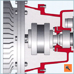
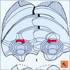
6.4 Rotating screw compressor
The main components of the rotating screw compressor are two screw rotors
within the case that encloses them firmly.
Here, the rotor tooth spaces form the compression volume.
Compression (without valves) is controlled via suction and pressure grooves
at the ends of the case.
There are oil-free and oil-injected rotating screw compressors.
Rotating screw compressors with oil-free compression volumes (compressed
air is completely oil-free) are designed for final pressures up to 3 b single-stage,
for higher pressure values double-stage (multi-stage).
Oil-injected rotating screw compressors can reach a final pressure of up
to 14 b at single-stage constructions. In order to be able to reach higher
values of final pressure double-stage variants are used as well.
As regards oil-injected rotating screw compressors the oil is used for sealing,
cooling and lubricating.
The control of the rotating screw compressor is carried out by intermittent
duty control and idle speed control. The load stages full load and idle speed
are always possible to run. As regards oil-injected machines control can
be performed by drainage coil adjustment.
Furthermore, you can also get speed-controlled compressors that can be adjusted
in such a way that the respectively required amount of air will always be
available.
Apart from the prescribed safety valves further monitoring units normally
exist, for instance the monitoring of compressor temperature, engine temperature,
pressures, power consumption, etc.
If one of the fuses reacts during operation, the compressor unit will be
usually switched off automatically.
|